
- #CETUS3D EXTENDED INSTALL#
- #CETUS3D EXTENDED UPDATE#
- #CETUS3D EXTENDED UPGRADE#
- #CETUS3D EXTENDED SOFTWARE#
#CETUS3D EXTENDED SOFTWARE#
Init via software is working and the endstops are working too. the hardware Init switch did not work anymore !!!!!! Therefore I hab to drill 4 more holes in the Baseplate to shift the Mainboard about 5mm to the middle.Īfter installing all the hardware I flashed the CPU with When the Mainboard was installed it was too close to the baseplate edge so that I could not put the Cover back on again. MK3 Standard Version ROM:įor the z axis I had to use the original cap to make a hole for the endstop because the linear rail from my printer seems to be shorter (the black part is the new one from the link above (didn't fit).
#CETUS3D EXTENDED UPDATE#
Lock the extruder cable along the Z-axisĬPU rom must be updated before the machine is usable, please refer to following info to update your rom.
#CETUS3D EXTENDED UPGRADE#
This ribbon cable is important for temprature control of heated bed upgrade and autoleveling.ġ0.1 Insert the antenna holder into the slot of the back of machine, turn it 90 degrees to lock it in position.ġ0.2 Insert the antenna into the holder and connect the other end to CPU.ġ0.3 Make sure the cables are well sorted, no tangling.

Insert the cable into the connector, metal pins facing to mainboard.ĩ.5 Fold the cable into shape like the red line indicated below.ĩ.6 Insert the ribbon cable through the space between motor and Z-axis bracket.ĩ.7 Fold the cable upward and insert into the connector, metal pins facing toward extension board. Follow the color.ĩ.2 Connect the limit switches from extension PCB to mainboard, using the included relay cable.ĩ.3 Connect the power cable from extension PCB to mainboardĩ.4 Loosen the connector (labelled as " Platform Heater) for ribbon cable.
#CETUS3D EXTENDED INSTALL#
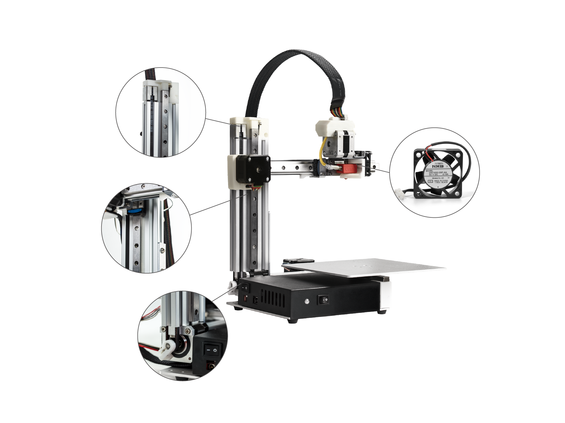
Install MK3 Z-axis Cap and Limit Switch.ĩ.1 Connec Z-limit switch and Y-limit switch to the extension board. Installation Guide of Extension PCB for Cetus MK3ĭetailed Guidance on Extension Board Installation and Limited Switch Issuesħ.2 Slide the extension board into extrusion slot. Install limit switch holder onto the Y-axis motor.Ħ.1 Open the slot cover on the back of the printer.Ħ.2 Press the holder into the slot, install the limit switch.Ħ.3 Position the motor cable and limit switch cable into the slot and press fit the slot cover.Ĭhapter 4. Remove the original printed part and the screw on the motor.ĥ.3. Install the limit switch on the holder.ĥ.2. Install the New Y Limit Switch Triggerĥ.1. Do not remove the screw from the belt, keep it on the belt!Ĥ.3. Lossen the screw on the back of the belt, remove the printed part.

Install Y-axis Limit Switch and Trigger.Ĥ.2. Connect Ground Cable (reduce risk of static charge damage to electronics) Install MK3 Mainboard, CPU and SD card.ģ.4. Remove the 4 screws on mainboard, unplug the extruder cable, motor cables and remove the mainboard.ģ.2 Install the Mainboard Adaptor and MK3 Mainboard.ģ.3. Before remove the CPU, discharging yourself is recommended, also be careful not to bend the pin of the CPU board.Ģ.6. Remove the power cable and the initialization button cable.Ģ.4. Remove the platform by removing the 3 scerws.Ģ.2 Remove the 4 screws to the bottom of machine.Ģ.3. Print Plastic Parts Required for Upgradeīefore dissasembling everything, printer out the parts required.ĭownload the following file for the printable parts:Ģ.1. User have to use the 220W Power Supply (sku:XS028). After upgrade, if user install the heated build platform, original power supply cannot be used to supply power to the machine.


 0 kommentar(er)
